User Manual
Please refer to the image below:
Installation
House the FHX-1 in a Eurorack case of your choosing. The power connector is Doepfer standard. If using the power cable supplied with the FHX-1, the connector is keyed and will only insert into the FHX-1 the correct way round, in which case the red edge of the cable is nearest the edge of the PCB, and carries -12V. ("-12V" is marked on the PCB itself next to this end of the connector.) Be sure to connect the other end of the power cable correctly, again so -12V corresponds to the red stripe on the cable.
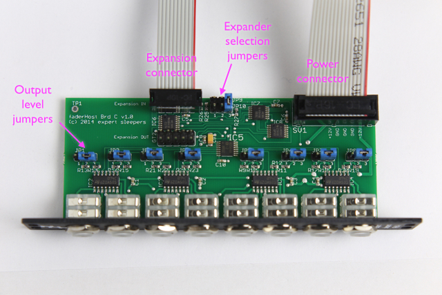
The FHX-1 also needs to be connected to an FH-1 or FH-2 module via its "Expansion IN" connector. A 10-way cable is supplied with the FHX-1. With this cable fitted as shown above, the red stripe should be oriented at the other end in the same way i.e. with the red stripe down.
Note: while the 10-way connector on the FHX-1 may look like the power connector on some Doepfer modules, it is not wired the same. If you connect this to a Doepfer power bus, you will almost certainly fuse the power supply and fry the FHX-1. This connector is only to be used for connecting the FHX-1 to an FH-1 or FH-2.
When multiple FHX-1s are to be driven from a single FH-1 or FH-2, they are daisy-chained. The first connection is from the FH-1 or FH-2 to the first FHX-1's Expansion IN connector. The second connection is from the first FHX-1's Expansion OUT connector to the second FHX-1's Expansion IN connector. Further FHX-1s are connected in the same manner. All the expansion cables are oriented the same way - if you find yourself twisting the cables, chances are you're inserting the ends incorrectly. With a row of FH-1/FHX-1s, all the cables should stay flat.
Note that each FHX-1 requires its own individual power connector as well as the expansion connector.
Jumpers
There are 11 possible jumper positions on the FHX-1's PCB.
Output level jumpers
The 8 jumpers numbered JP1-8, situated in a row above the jack sockets, set the voltage range for each output. The options are:
- ±5V - jumper in lower position (factory default setting)
- 0-10V - jumper in upper position
- 0-5V - jumper not fitted
Expander selection jumpers
Next to the Expansion IN connector are two 3-way jumper blocks numbered JP9 & JP10. These are used to select which of the possible 8 expansion channels this FHX-1 responds to.
Channel 'zero' is the FH-1 or FH-2 itself. Channels 1-7 are the expansions channels, corresponding to outputs 9-64.
The expansion channel is selected by placing jumper links in a binary pattern between JP9 and JP10. As shipped (and as in the photo above), a jumper is placed in position '3', which corresponds to a value of 1, so the FHX-1 responds on expansion channel 1.
The position labelled '2' corresponds to a value of 2, and the position labelled '1' corresponds to a value of 4. Therefore, the 7 expansion channels are selected by placing jumpers as in the table below:
| 1 | 2 | 3 | |
|---|---|---|---|
| Expansion channel 1 | | | ||
| Expansion channel 2 | | | ||
| Expansion channel 3 | | | | | |
| Expansion channel 4 | | | ||
| Expansion channel 5 | | | | | |
| Expansion channel 6 | | | | | |
| Expansion channel 7 | | | | | | |