ES-6 CV/Lightpipe Interface
User Manual
Installation
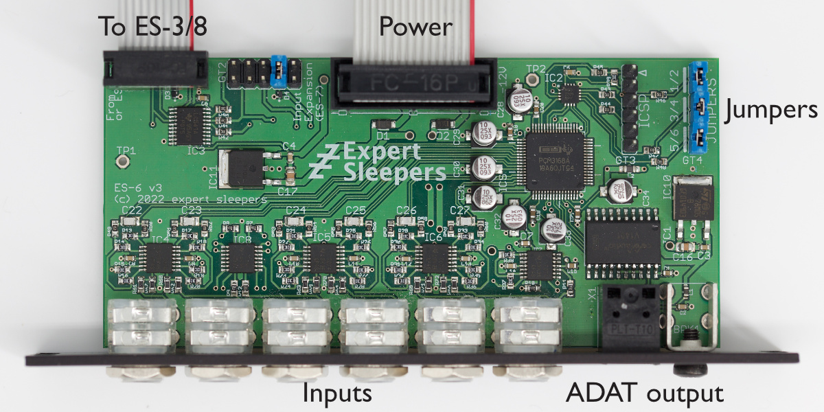
House the ES-6 in a Eurorack case of your choosing. The power connector is Doepfer standard. If using the power cable supplied with the ES-6, the connector is keyed and will only insert into the ES-6 the correct way round, in which case the red edge of the cable is nearest the bottom of the PCB, and carries -12V. ("-12V" is marked on the PCB itself next to this end of the connector.) Be sure to connect the other end of the power cable correctly, again so -12V corresponds to the red stripe on the cable.
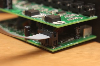
The ES-6 also needs to be connected to an ES-3 or ES-8 module. Exactly how this happens depends on the module and its revision:
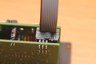
ES-3 mk3/mk4 or ES-8 - connection is via the supplied 10-way cable to the header on the ES-3 or ES-8 PCB (see image below). Fit the ribbon cable with the red stripe down at both ends.
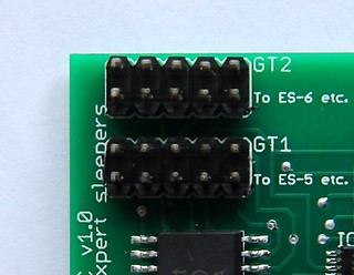
ES-3 mk2 - connection is via the supplied 10-way cable to the header on the ES-3 mk2 PCB (see image below). You may find it helpful to loosen the screws that attach the PCB to the module's panel while fitting the cable. Note that the six conductors on the side of the cable with the red stripe engage with the 6-way header on the ES-3; the four unused conductors hang over the small IC at the edge of the board.
ES-3 mk1 - requires an equivalent connection to be soldered to the ES-3 PCB. Details to follow.
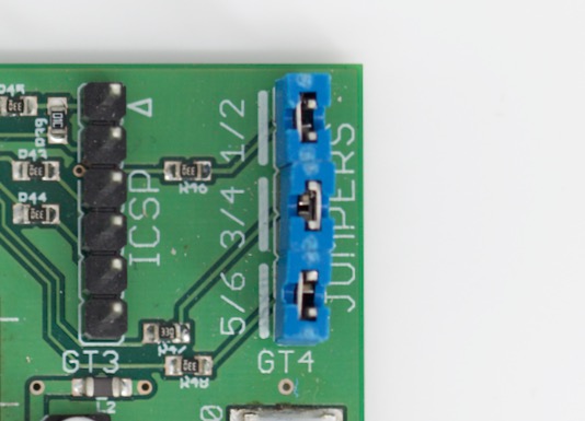
Jumpers (ES-6 mk3 only)
The ES-6 mk3 has a header on the board labelled GT4. Fitting jumpers on the pairs of pins indicated enables DC blocking on the respective input channels. Removing the jumper disables DC blocking on that input pair, allowing the inputs to be used for CV.
From the factory, all three jumpers are fitted (DC blocking enabled), which is the most appropriate setup for audio use.
Connecting Expansion Modules
The ES-6 has a connector for expansion modules such as the ES-7 CV Input Expander. Please turn the power off before connecting or disconnecting the expansion modules.
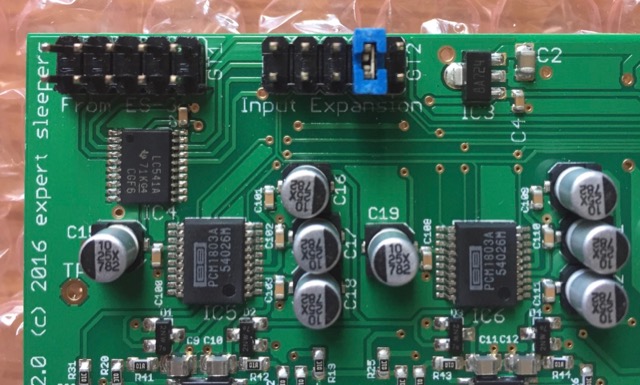
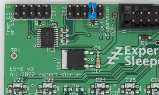
You may find your ES-6 comes with a jumper fitted across two of the pins on the 'Input Expansion' header. This is to prevent spurious input when an expander is not connected. If fitted, it should be across the two pins as in the photo above, not any other pins.