ES-4 SPDIF/CV Interface
User Manual
Software
Please proceed to the downloads page to download the Silent Way software, and its user manual.For more tutorial videos, please see the tutorials page.
ES-4
Please refer to the image below (click to enlarge):
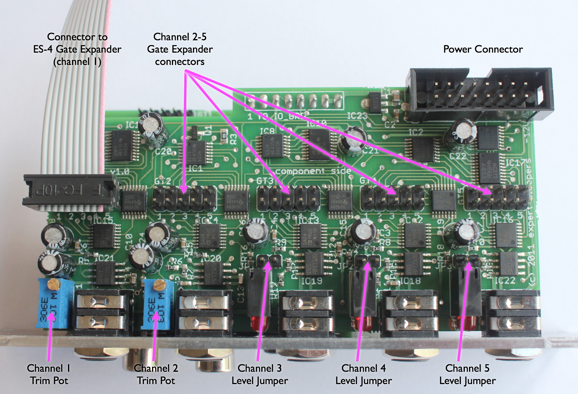
Installation
House the ES-4 in a Eurorack case of your choosing. The power connector is Doepfer standard. If using the power cable supplied with the ES-4, the connector is keyed and will only insert into the ES-4 the correct way round, in which case the red edge of the cable is nearest the edge of the PCB, and carries -12V. ("-12V" is marked on the PCB itself next to this end of the connector.) Be sure to connect the other end of the power cable correctly, again so -12V corresponds to the red stripe on the cable.The input connector is connected to the coaxial S/PDIF output of your audio interface, using a standard 75ohm phono cable. The large LED below the S/PDIF connections on the panel lights if the ES-4 recognises a valid signal on its input. See this page for discussion on connecting to optical S/PDIF (including the MacBook Pro's built-in output).
The S/PDIF output connector is only used by certain expansion options e.g. the ES-7 CV Input Expander.
Level Jumpers
Before installing into your case, you may wish to use the supplied jumpers to adjust the output levels of channels 3, 4 & 5. Without the jumpers fitted (as shipped from the factory) these channels output 0V to +10V. With the jumper fitted, the channel outputs -5V to +5V.Please fit or remove the jumpers with the power turned off.
LEDs
Channels 3, 4 & 5 each have a pair of LEDs which glow proportionally to the output voltage. The right LED of each pair indicates positive output voltage; the left LED indicates negative voltage. Note that if the jumpers are fitted for 0-10V operation, the left LED will not light, since the voltage never goes negative.Calibration
Channels 1 & 2 are factory-calibrated to output 1V/octave when used with the ES-4 Silent Way plug-in. Most users should not need to adjust this calibration themselves. However, if for some reason you do wish to recalibrate, or if you want to use a non-standard tuning (e.g. 1.2V/octave for Buchla systems), the procedure is as follows. The procedure is the same for channels 1 & 2, and uses only the corresponding trim pot as noted in the image above.- Send note zero from the ES-4 controller software (equivalently, send nothing at all to the ES-4). Measure the output voltage of the channel to be calibrated. It will typically be in the low millivolt range.
- Send a note a whole number of octaves up. Go as many octaves up as you can, while still maintaining full accuracy on your voltmeter. For example, some voltmeters meaasure with mV accuracy up to about 2.5V, and then drop to 10mV accuracy. In this case, you would send a note 2 octaves above zero.
- Measure the output voltage and adjust the trim pot so the output in volts is equal to the octave gap, plus the offset measured in step 1.
Connecting Gate Expanders
The ES-4 has 5 connectors for ES-4 Gate Expanders - see below for details. Please turn the power off before connecting or disconnecting the Gate Expanders.ES-4 Gate Expander
Please refer to the image below (click to enlarge):

Installation
The ES-4 Gate Expander must be connected to an ES-4 module in order to function. A 10-way ribbon cable is supplied with the Gate Expander for this purpose. Please note the aligment of the cable in the images above. With the cable emerging at the back of the board, the red stripe is nearer the bottom (where 'bottom' is the higher-numbered output channel, 5 for the ES-4 and 8 for the Gate Expander).Note: while the 10-way connector on the Gate Expander may look like the power connector on some Doepfer modules, it is not wired the same. If you connect this to a Doepfer power bus, you will almost certainly fuse the power supply and fry the Gate Expander. This connector is only to be used for connecting the Gate Expander to an ES-4.
Auxiliary Power
In normal use, the Gate Expander draws its power from the connection to the ES-4. However, multiple Gate Expanders, all potentially driving 8 hungry module inputs, could put a great strain on the ES-4's own power connections. For this reason, the Gate Expander is also fitted with a standard 16-way power connector, which is Doepfer standard and identical to that on the ES-4. Use this connection if your system requires it.At the time of writing, it's hard to come up with hard-and-fast rules for when it would be a good idea to use the auxiliary power connector. This page wil be updated if and when more information comes to light.
Note: the +12V line on the auxiliary power connector and the 10-way connector to the ES-4 are one and the same on the Gate Expander. Therefore, if using the auxiliary power connector please attach it to the same power bus as the ES-4.
Level Jumpers
The Gate Expander outputs can be set to 5V or 12V levels. This choice can be made for channels 1 to 4 as a group, and for channels 5 to 8 as a group.For general usage in a Eurorack system, the 5V level is probably most appropriate, and the Gate Expander ships from the factory with both jumpers in the 5V position. You might find the 12V setting useful for vintage analogue gear, which often expect much higher gate voltages than modern designs.
The jumpers are fitted as in the above image, which shows channels 1-4 set for 5V and channels 5-8 set for 12V.
Note: the "12V" level simply outputs signals at the level of the incoming power. If you're using the Gate Expander in a non-Eurorack system with a different supply voltage, the "12V" level may not actually be 12V. E.g. in a 15V system, the gate outputs in "12V" mode will be 15V.
Please fit or remove the jumpers with the power turned off.